Activity diagram is designed to model the system's workflow.
The diagram can include nodes, which represent activities or actions, and edges, which represent the flow of control between activities.
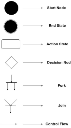
- Action: A step in the activity wherein the users or software perform a given task. - round-edged rectangles.
- Decision node: A conditional branch in the flow - diamond. It includes a single input and two or more outputs.
- Control flows: Another name for the connectors that show the flow between steps in the diagram. - Arrow
- Start node: Symbolizes the beginning of the activity. - black circle.
- End node: Represents the final step in the activity. - outlined black circle.
- Fork: Splits a single activity flow into two concurrent activities. - multiple arrowed lines from a join.
- Join: Combines two concurrent activities and re-introduces them to a flow where only one activity occurs at a time. - a thick vertical or horizontal lines joining to form one
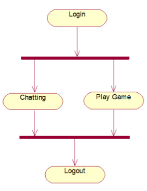
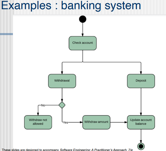
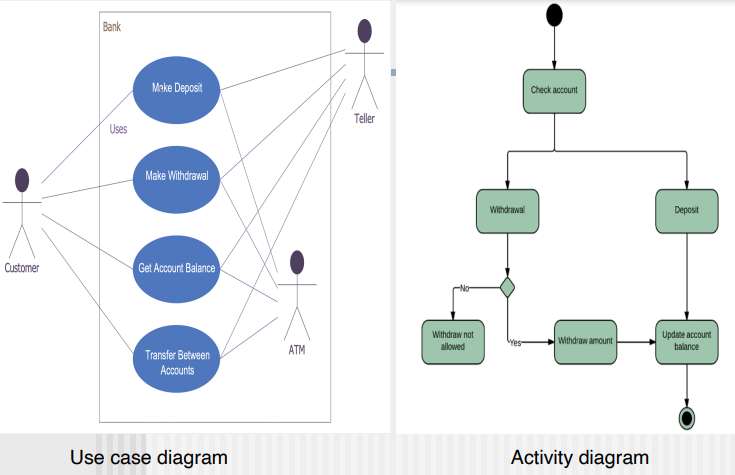
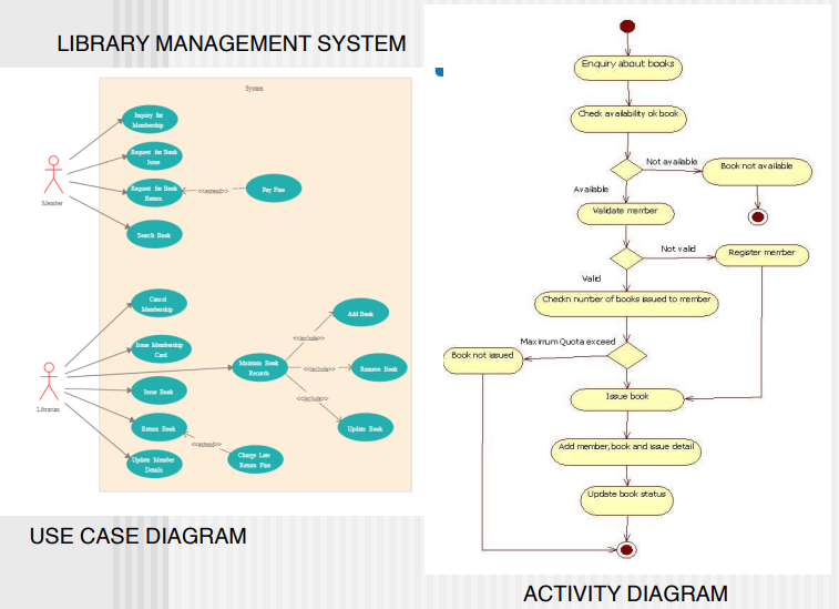
Examples: